文章目录
- 实验需求:
- 关键命令:
- 静态路由
- 默认路由
- 实验配置
- 接下来是配置pc的IP地址
- 静态路由的配置
- 保存
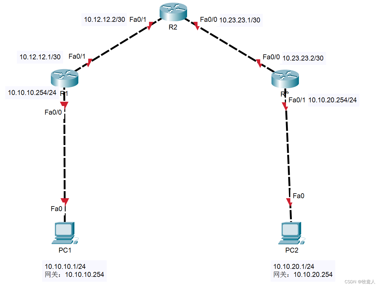
实验需求:
PC1 在 LAN1 中,PC2 在 LAN2 中,使用静态路由实现 pc1 和 pc2 之间的互相通信
本实验使用Cisco Packet Tracer 模拟器搭建
所有的路由器型号为“1841”
关键命令:
静态路由
ip route network mask ip-address/interface X[distance][permanent](目的网络) (目的网络掩码) (下一跳地址) (本地出接口)例:ip router 10.0.0.0 255.0.0.0 20.1.1.1
默认路由
ip router 0.0.0.0 0.0.0.0 ip-address(下一跳地址)/interface X (本地出接口)例: ip route 10.0.0.0 255.0.0.0 20.1
实验配置

直接no就行,
R1:
enable			\\进入配置视图
config terminal			\\进入管理员视图
hostname R1				\\修改设备名称
interface f0/0			\\进入接口视图
ip address 10.10.10.254 255.255.255.0		\\配置IP地址
no shutdown				\\开启接口
interface f0/1
ip address 10.12.12.1 255.255.255.252
no shutdownR2:
enable
config terminal
hostname R2
interface f0/1
ip address 10.12.12.2 255.255.255.252
no shutdown
interface f0/0
ip address 10.23.23.1 255.255.255.252
no shutdownR3:
enable
config terminal
hostname R3
interface f0/0
ip address 10.23.23.2 255.255.255.252
no shutdown
interface f0/1
ip address 10.10.20.254 255.255.255.0
no sh

这是路由器的接口都开启时的状态
接下来是配置pc的IP地址
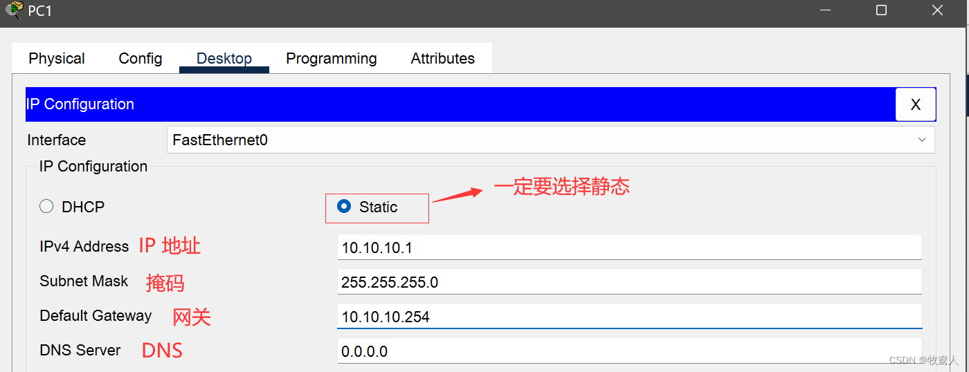

现在以及配置完pc的IP地址
如果此时去用 pc1 去 ping ,pc2 能不能通?

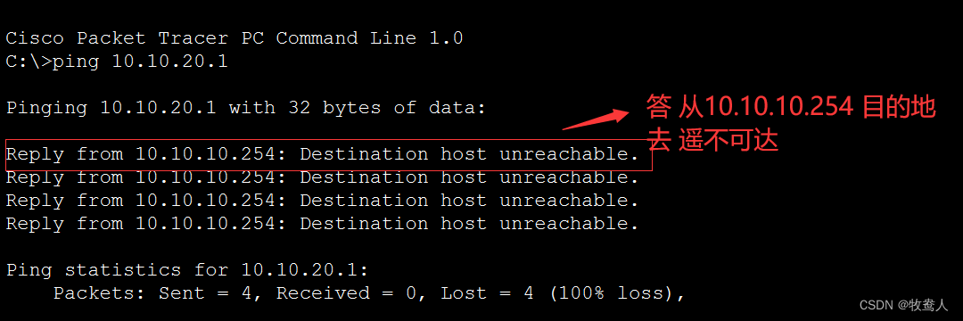
上图可以看出 R1 ping 不通 R2
这是为什么呢?
静态路由的配置
进入管理员视图配置:
R1:
R1(config)#ip route 10.10.20.0 255.255.255.0 10.12.12.0
R1(config)#ip route 10.23.23.0 255.255.255.0 10.12.12.2
R2:
R2(config)#ip route 10.10.20.0 255.255.255.0 10.23.23.2
R2(config)#ip route 10.10.10.0 255.255.255.0 10.12.12.1
R3:
R3(config)#ip route 10.12.12.0 255.255.255.0 10.23.23.1
R3(config)#ip route 10.10.10.0 255.255.255.0 10.23.23.1
此时可以发现3个路由器都有两条静态路由了
配置视图:
#R1:
R1#sh ip route
Codes: C - connected, S - static, I - IGRP, R - RIP, M - mobile, B - BGPD - EIGRP, EX - EIGRP external, O - OSPF, IA - OSPF inter areaN1 - OSPF NSSA external type 1, N2 - OSPF NSSA external type 2E1 - OSPF external type 1, E2 - OSPF external type 2, E - EGPi - IS-IS, L1 - IS-IS level-1, L2 - IS-IS level-2, ia - IS-IS inter area* - candidate default, U - per-user static route, o - ODRP - periodic downloaded static routeGateway of last resort is not set10.0.0.0/8 is variably subnetted, 4 subnets, 2 masks
C       10.10.10.0/24 is directly connected, FastEthernet0/0
S       10.10.20.0/24 [1/0] via 10.12.12.2						\\此类“S”开头的为静态路由
C       10.12.12.0/30 is directly connected, FastEthernet0/1
S       10.23.23.0/24 [1/0] via 10.12.12.2#R2:
R2#sh ip route
Codes: C - connected, S - static, I - IGRP, R - RIP, M - mobile, B - BGPD - EIGRP, EX - EIGRP external, O - OSPF, IA - OSPF inter areaN1 - OSPF NSSA external type 1, N2 - OSPF NSSA external type 2E1 - OSPF external type 1, E2 - OSPF external type 2, E - EGPi - IS-IS, L1 - IS-IS level-1, L2 - IS-IS level-2, ia - IS-IS inter area* - candidate default, U - per-user static route, o - ODRP - periodic downloaded static routeGateway of last resort is not set10.0.0.0/8 is variably subnetted, 4 subnets, 2 masks
S       10.10.10.0/24 [1/0] via 10.12.12.1
S       10.10.20.0/24 [1/0] via 10.23.23.2
C       10.12.12.0/30 is directly connected, FastEthernet0/1
C       10.23.23.0/30 is directly connected, FastEthernet0/0#R3:
R3#sh ip route
Codes: C - connected, S - static, I - IGRP, R - RIP, M - mobile, B - BGPD - EIGRP, EX - EIGRP external, O - OSPF, IA - OSPF inter areaN1 - OSPF NSSA external type 1, N2 - OSPF NSSA external type 2E1 - OSPF external type 1, E2 - OSPF external type 2, E - EGPi - IS-IS, L1 - IS-IS level-1, L2 - IS-IS level-2, ia - IS-IS inter area* - candidate default, U - per-user static route, o - ODRP - periodic downloaded static routeGateway of last resort is not set10.0.0.0/8 is variably subnetted, 4 subnets, 2 masks
S       10.10.10.0/24 [1/0] via 10.23.23.1
C       10.10.20.0/24 is directly connected, FastEthernet0/1
S       10.12.12.0/24 [1/0] via 10.23.23.1
C       10.23.23.0/30 is directly connected, FastEthernet0/0
当路由器有路由信息后我们再去ping,能不能通?

现在可以看到pc1可以ping通pc2了,到此时我们的配置已经完成。
保存
现在需要保存拓扑图,在保存拓扑图之前我们先要把路由器的配置
在配置模式下输入write
R1#write
Building configuration...
[OK]
依次在路由器R1、R2、R3上输入write保存配置命令
然后再模拟器的左上角找到File
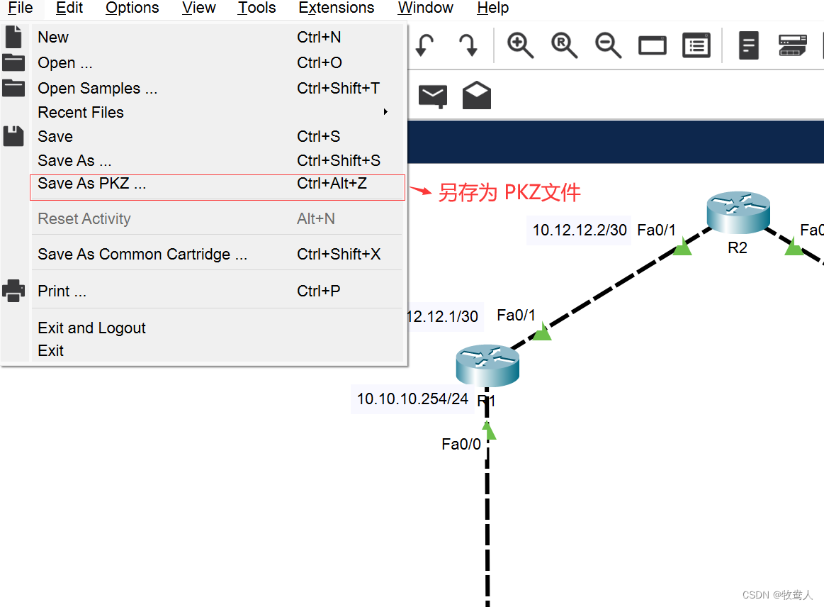
或者点击左上角的
都可以保存

保存了配置可以方便以后的查看 也可以已文件的形式发送给好友


![洛谷千题详解 | P1018 [NOIP2000 提高组] 乘积最大【C++、Python、Java、pascal语言】](https://img-blog.csdnimg.cn/img_convert/443d6920a7fea48f91a389bb5103e7fa.png)
![苯丙氨酸甲酯双三氟甲基磺酰亚胺[PheC1][Tf2N]氨基酸酯离子液体](https://img-blog.csdnimg.cn/73fce3fac4094595b2a50e872414056a.png)