I2CI^2CI2C通讯
I2CI^2CI2C is a two-wire interface comprised of the signals serial data (SDA) and serial clock (SCL). In general, the lines are open-drain and bi-directional. In a generalized I-C interface implementation, attached devices can be a master or a slave. The master device puts the slave address on the bus, and the slave device with the matching address acknowledges the master.
The MPU-60X0 always operates as a slave device when communicating to the system processor, which thus acts as the master. SDA and SCL lines typically need pull-up resistors to VDD. The maximum bus speed is 400 kHz.
The slave address of the MPU-60X0 is b110100X(104 or 105) which is 7 bits long. The LSB bit of the 7 bit address is determined by the logic level on pin AD0. This allows two MPU-60X0s to be connected to the same IC bus. When used in this configuration, the address of the one of the devices should be b1101000 (pin AD0 is logic low) and the address of the other should be b1101001 (pin AD0 is logic high).
I2CI^2CI2C Communications Protocol
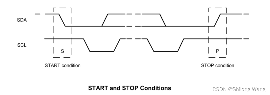
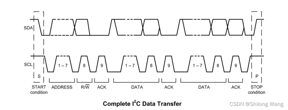
Communication on the I2CI^2CI2C bus starts when the master puts the START condition (S) on the bus, which is defined as a HIGH-to-LOW transition of the SDA line while SCL line is HIGH (see figure below). The bus is considered to be busy until the master puts a STOP condition § on the bus, which is defined as a LOW-to-HIGH transition on the SDA line while SCL is HIGH (see figure below).
Additionally, the bus remains busy if a repeated START (Sr) is generated instead of a STOP condition.
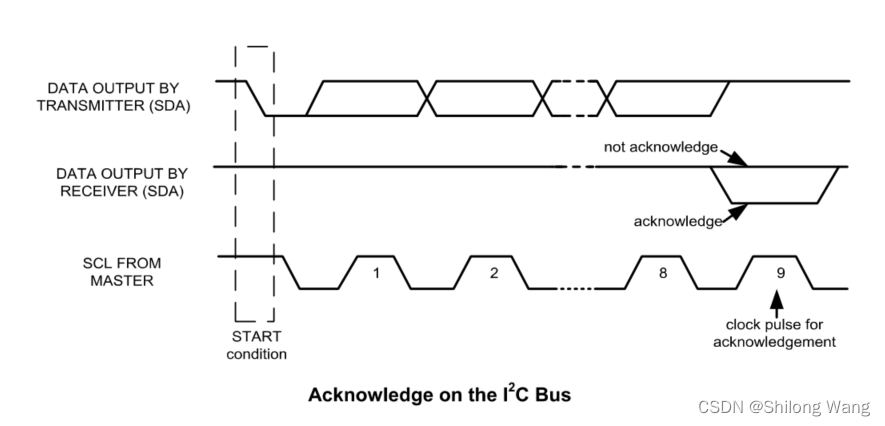
I2C data bytes are defined to be 8-bits long. There is no restriction to the number of bytes transmitted per data transfer. Each byte transferred must be followed by an acknowledge (ACK) signal. The clock for the acknowledge signal is generated by the master, while the receiver generates the actual acknowledge signal by pulling down SDA and holding it low during the HIGH portion of the acknowledge clock pulse.
If a slave is busy and cannot transmit or receive another byte of data until some other task has been
performed, it can hold SCL LOW, thus forcing the master into a wait state. Normal data transfer resumes when the slave is ready, and releases the clock line (refer to the following figure).
Communications
After beginning communications with the START condition (S), the master sends a 7-bit slave address
followed by an 8th8^{th}8th bit, the read/write bit. The read/write bit indicates whether the master is receiving data from or is writing to the slave device. Then, the master releases the SDA line and waits for the acknowledge signal (ACK) from the slave device. Each byte transferred must be followed by an acknowledge bit. To acknowledge, the slave device pulls the SDA line LOW and keeps it LOW for the high period of the SCL line.
Data transmission is always terminated by the master with a STOP condition §, thus freeing the
communications line. However, the master can generate a repeated START condition (Sr), and address
another slave without first generating a STOP condition §. A LOW to HIGH transition on the SDA line while SCL is HIGH defines the stop condition. AlI SDA changes should take place when SCL is low, with the exception of start and stop conditions.
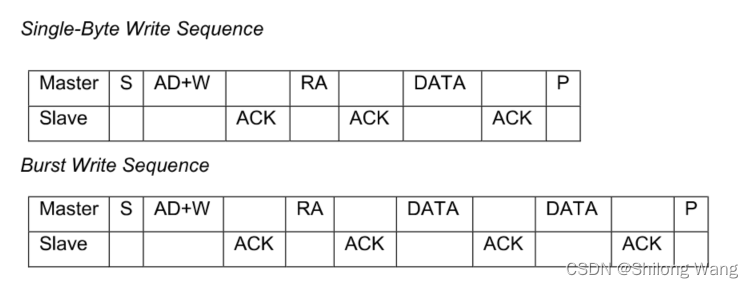
To write the internal MPU-60X0 registers, the master transmits the start condition (S), followed by the I2CI^2CI2C address and the write bit (0). At the 9th9^{th}9th clock cycle (when the clock is high), the MPU-60X0 acknowledges the transfer. Then the master puts the register address (RA) on the bus. After the MPU-60X0 acknowledges the reception of the register address, the master puts the register data onto the bus. This is followed by the ACK signal, and data transfer may be concluded by the stop condition §. To write multiple bytes after the last ACK signal, the master can continue outputting data rather than transmitting a stop signal. In this case, the MPU-60X0 automatically increments the register address and loads the data to the appropriate register. The following figures show single and two-byte write sequences.
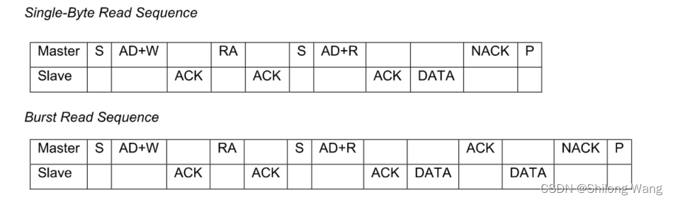
To read the internal MPU-60X0 registers, the master sends a start condition, followed by the I2CI^2CI2C address and a write bit(0), and then the register address that is going to be read. Upon receiving the ACK signal from the MPU-60X0, the master transmits a start signal followed by the slave address and read bit(1). As a result, the MPU-60X0 sends an ACK signal and the data. The communication ends with a not acknowledge (NACK) signal and a stop bit from master. The NACK condition is defined such that the SDA line remains high at the 9th9^{th}9th clock cycle. The following figures show single and two-byte read sequences.
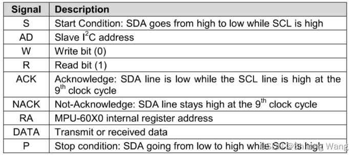
除了开始位(Start)和停止位(stop),所有SDA的信号变化都必须在SCL的低电平完成。
从设备应答使用低电平(ACK),主设备应答采用高电平(NACK)
时钟SCL的上升沿作为读取的时刻,时钟SCL的下降沿作为发送的时刻
寄存器
- 0x3B,加速度计的X轴分量ACC_X
- 0x3D,加速度计的Y轴分量ACC_Y
- 0x3F,加速度计的Z轴分量ACC_Z
- 0x41,当前温度TEMP
- 0x43,绕X轴旋转的角速度GYR_X
- 0x45,绕Y轴旋转的角速度GYR_Y
- 0x47,绕Z轴旋转的角速度GYR_Z
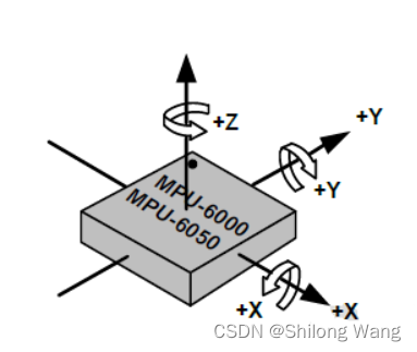
加速度计的三轴分量ACC_X、ACC_Y和ACC_Z均为16位有符号整数,分别表示器件在三个轴向上的加速度,取负值时加速度沿座标轴负向,取正值时沿正向。
配置寄存器
加速度配置寄存器
三个加速度分量均以重力加速度g的倍数为单位,能够表示的加速度范围,即倍率可以统一设定,有4个可选倍率:2g、4g、8g、16g。以ACC_X为例,若倍率设定为2g(默认),则意味着ACC_X取最小值-32768时,当前加速度为沿X轴正方向2倍的重力加速度;若设定为4g,取-32768时表示沿X轴正方向4倍的重力加速度,以此类推。显然,倍率越低精度越好,倍率越高表示的范围越大,这要根据具体的应用来设定
| Register (Hex) | Register (Decimal) | Bit7 | Bit6 | Bit5 | Bit4 | Bit3 | Bit2 | Bit1 | Bit0 |
|---|---|---|---|---|---|---|---|---|---|
| 1C | 28 | XA_ST | YA_ST | ZA_ST | AFS_SEL[1] | AFS_SEL[1] |
Parameters:
- XA_ST: When set to 1, the X- Axis accelerometer performs self test.
- YA_ST: When set to 1, the Y- Axis accelerometer performs self test.
- ZA_ST: When set to 1, the Z- Axis accelerometer performs self test.
- AFS_SEL: 2-bit unsigned value. Selects the full scale range of accelerometers
| AFS_SEL | Full Scale Range |
|---|---|
| 0 | ± 2g |
| 1 | ± 4g |
| 2 | ± 8g |
| 3 | ± 16g |
Wire.beginTransmission(0x68); //开启MPU-6050的传输
Wire.write(0x1C); //加速度倍率寄存器的地址
Wire.requestFrom(0x68, 1, true); //先读出原配置
unsigned char acc_conf = Wire.read();
acc_conf = ((acc_conf & 0xE7) | (f << 3));
Wire.write(acc_conf)
Wire.endTransmission(true); //结束传输,true表示释放总线
陀螺仪配置寄存器
绕X、Y和Z三个座标轴旋转的角速度分量GYR_X、GYR_Y和GYR_Z均为16位有符号整数。从原点向旋转轴方向看去,取正值时为顺时针旋转,取负值时为逆时针旋转。
三个角速度分量均以“度/秒”为单位,能够表示的角速度范围,即倍率可统一设定,有4个可选倍率:250度/秒、500度/秒、1000度/秒、2000度/秒。以GYR_X为例,若倍率设定为250度/秒,则意味着GYR取正最大值32768时,当前角速度为顺时针250度/秒;若设定为500度/秒,取32768时表示当前角速度为顺时针500度/秒。显然,倍率越低精度越好,倍率越高表示的范围越大。
以GYR_X为例,若当前设定的角速度倍率为1000度/秒,那么将GRY_X读数换算为角速度(顺时针)的公式为:gx=1000×GYRX32768g_x=1000\times \dfrac{GYR_X}{32768}gx=1000×32768GYRX。
| Register (Hex) | Register (Decimal) | Bit7 | Bit6 | Bit5 | Bit4 | Bit3 | Bit2 | Bit1 | Bit0 |
|---|---|---|---|---|---|---|---|---|---|
| 1B | 27 | XG_ST | YG_ST | ZG_ST | FS_SEL[1] | FS_SEL[0] |
| FS_SEL | Full Scale Range |
|---|---|
| 0 | ± 250 °/s |
| 1 | ± 500 °/s |
| 2 | ± 1000 °/s |
| 3 | ± 2000 °/s |
Parameters:
- XG_ST :Setting this bit causes the X axis gyroscope to perform self test.
- YG_ST :Setting this bit causes the Y axis gyroscope to perform self test.
- ZG_ST Setting this bit causes the Z axis gyroscope to perform self test.
- FS_SEL 2-bit unsigned value. Selects the full scale range of gyroscopes
Register 107 – Power Management 1
This register allows the user to configure the power mode and clock source. It also provides a bit for resetting the entire device, and a bit for disabling the temperature sensor.
| Register (Hex) | Register (Decimal) | Bit7 | Bit6 | Bit5 | Bit4 | Bit3 | Bit2 | Bit1 | Bit0 |
|---|---|---|---|---|---|---|---|---|---|
| 6B | 107 | DEVICE _RESET | SLEEP | CYCLE | - | TEMP_DIS | CLKSEL[2] | CLKSEL[1] | CLKSEL[0] |
| CLKSEL | Clock Source |
|---|---|
| 0 | Internal 8MHz oscillator |
| 1 | PLL with X axis gyroscope reference |
| 2 | PLL with Y axis gyroscope reference |
| 3 | PLL with Z axis gyroscope reference |
| 4 | PLL with external 32.768kHz reference |
| 5 | PLL with external 19.2MHz reference |
| 6 | Reserved |
| 7 | Stops the clock and keeps the timing generator in reset |
Parameters:
- DEVICE_RESET
When set to 1, this bit resets all internal registers to their default values. The bit automatically clears to 0 once the reset is done. The default values for each register can be found in Section 3. - SLEEP: When set to 1, this bit puts the MPU-60X0 into sleep mode.
- CYCLE: When this bit is set to 1 and SLEEP is disabled, the MPU-60X0 will cycle between sleep mode and waking up to take a single sample of data from active sensors at a rate determined by LP_WAKE_CTRL (register 108).
- TEMP_DIS: When set to 1, this bit disables the temperature sensor.
- CLKSEL: 3-bit unsigned value. Specifies the clock source of the device.
X轴Roll轴,Y轴Pitch轴
pitch=arccos(accy2+accz2g)ifaccx>0,pitch<0pitch=\arccos(\dfrac{\sqrt{acc_y^2+acc_z^2}}{g})\quad if \ acc_x>0,pitch<0pitch=arccos(gaccy2+accz2)if accx>0,pitch<0
roll=arccos(accx2+accz2g)ifaccy<0,roll<0roll=\arccos(\dfrac{\sqrt{acc_x^2+acc_z^2}}{g})\quad if \ acc_y<0,roll<0roll=arccos(gaccx2+accz2)if accy<0,roll<0
Arduino库Wire.h
| Board | I2C / TWI pins |
|---|---|
| Uno, Ethernet | A4 (SDA), A5 (SCL) |
Wire.requestFrom()
-
Syntax
Wire.requestFrom(address, quantity)
Wire.requestFrom(address, quantity, stop) -
Parameters
address: the 7-bit address of the device to request bytes from
quantity: the number of bytes to request
stop : boolean. true will send a stop message after the request, releasing the bus. false will continually send a restart after the request, keeping the connection active.
-
Returns
byte : the number of bytes returned from the slave device
Wire.available()
-
Description
Returns the number of bytes available for retrieval with read(). This should be called on a master device after a call to requestFrom() or on a slave inside the onReceive() handler.
available() inherits from the Stream utility class.
-
Parameters
None
-
Returns
The number of bytes available for reading.
Wire.beginTransmission(address)
-
Description
Begin a transmission to the I2C slave device with the given address. Subsequently, queue bytes for transmission with the write() function and transmit them by calling endTransmission().
-
Parameters
address: the 7-bit address of the device to transmit to
-
Returns
None
Wire.endTransmission()
-
Description
Ends a transmission to a slave device that was begun by beginTransmission() and transmits the bytes that were queued by write().
As of Arduino 1.0.1, endTransmission() accepts a boolean argument changing its behavior for compatibility with certain I2C devices.
If true, endTransmission() sends a stop message after transmission, releasing the I2C bus.
If false, endTransmission() sends a restart message after transmission. The bus will not be released, which prevents another master device from transmitting between messages. This allows one master device to send multiple transmissions while in control.
The default value is true.
-
Syntax
Wire.endTransmission()
Wire.endTransmission(stop)
- Parameters
stop : boolean. true will send a stop message, releasing the bus after transmission. false will send a restart, keeping the connection active.
-
Returns
byte, which indicates the status of the transmission:
- 0:success
- 1:data too long to fit in transmit buffer
- 2:received NACK on transmit of address
- 3:received NACK on transmit of data
- 4:other error
Wire.write()
-
Description
Writes data from a slave device in response to a request from a master, or queues bytes for transmission from a master to slave device (in-between calls to beginTransmission() and endTransmission()).
-
Syntax
Wire.write(value)
Wire.write(string)
Wire.write(data, length) -
Parameters
value: a value to send as a single byte
string: a string to send as a series of bytes
data: an array of data to send as bytes
length: the number of bytes to transmit
-
Returns
byte: write() will return the number of bytes written, though reading that number is optional
#include <Wire.h>
byte val = 0;
void setup()
{Wire.begin(); // join i2c bus
}void loop()
{Wire.beginTransmission(44); // transmit to device #44 (0x2c)// device address is specified in datasheetWire.write(val);             // sends value byte  Wire.endTransmission();     // stop transmittingval++;        // increment valueif(val == 64) // if reached 64th position (max){val = 0;    // start over from lowest value}delay(500);
}
Wire.read()
-
Description
Reads a byte that was transmitted from a slave device to a master after a call to requestFrom() or was transmitted from a master to a slave. read() inherits from the Stream utility class.
-
Syntax
Wire.read()
-
Parameters
none
-
Returns
The next byte received
#include <Wire.h>
void setup()
{Wire.begin();        // join i2c bus (address optional for master)Serial.begin(9600);  // start serial for output
}void loop()
{Wire.requestFrom(2, 6);    // request 6 bytes from slave device #2while(Wire.available())    // slave may send less than requested{char c = Wire.read();    // receive a byte as characterSerial.print(c);         // print the character}delay(500);
}
Wire.setClock()
-
Description
This function modifies the clock frequency for I2C communication. I2C slave devices have no minimum working clock frequency, however 100KHz is usually the baseline.
-
Syntax
Wire.setClock(clockFrequency)
-
Parameters
clockFrequency: the value (in Hertz) of desired communication clock. Accepted values are 100000 (standard mode) and 400000 (fast mode). Some processors also support 10000 (low speed mode), 1000000 (fast mode plus) and 3400000 (high speed mode). Please refer to the specific processor documentation to make sure the desired mode is supported.
-
Returns
None
Wire.onReceive(handler)
-
Description
Registers(注册) a function to be called when a slave device receives a transmission from a master.
-
Parameters
handler: the function to be called when the slave receives data; this should take a single int parameter (the number of bytes read from the master) and return nothing, e.g.:
void myHandler(int numBytes) -
Returns
None
Wire.onRequest(handler)
-
Description
Register a function to be called when a master requests data from this slave device.
-
Parameters
handler: the function to be called, takes no parameters and returns nothing, e.g.:
void myHandler() -
Returns
None