【 声明:版权所有,欢迎转载,请勿用于商业用途。 联系信箱:feixiaoxing @163.com】
除了通用计算器负责控制和计算之外,cpu如果需要正常有序地运行,还需要一定地协处理器来帮助完成对应地工作。在mips下面,这样地协处理器称之为cp0。协处理器的工作一般包括这几个方面,
1)处理中断和异常;
2)处理mmu和tlb;
3)处理cache;
4)处理其他cpu的相关属性。
之前我们在谈到乘法和除法的时候,涉及到hi和lo这两个寄存器。其实,cp0的处理方法和他们是差不多的。如果是mf读操作,那么这个动作是在exe阶段完成的;如果是写操作,那么这个动作也是在wb阶段完成的。
1、准备cp0_reg.v
`include "defines.v"module cp0_reg(input	wire										clk,input wire										rst,input wire                    we_i,input wire[4:0]               waddr_i,input wire[4:0]               raddr_i,input wire[`RegBus]           data_i,//	input wire[31:0]              excepttype_i,input wire[5:0]               int_i,
//	input wire[`RegBus]           current_inst_addr_i,
//	input wire                    is_in_delayslot_i,output reg[`RegBus]           data_o,output reg[`RegBus]           count_o,output reg[`RegBus]           compare_o,output reg[`RegBus]           status_o,output reg[`RegBus]           cause_o,output reg[`RegBus]           epc_o,output reg[`RegBus]           config_o,output reg[`RegBus]           prid_o,output reg                   timer_int_o    );always @ (posedge clk) beginif(rst == `RstEnable) begincount_o <= `ZeroWord;compare_o <= `ZeroWord;//status寄存器的CU为0001,表示协处理器CP0存在status_o <= 32'b00010000000000000000000000000000;cause_o <= `ZeroWord;epc_o <= `ZeroWord;//config寄存器的BE为1,表示Big-Endian;MT为00,表示没有MMUconfig_o <= 32'b00000000000000001000000000000000;//制作者是L,对应的是0x48,类型是0x1,基本类型,版本号是1.0prid_o <= 32'b00000000010011000000000100000010;timer_int_o <= `InterruptNotAssert;end else begincount_o <= count_o + 1 ;cause_o[15:10] <= int_i;if(compare_o != `ZeroWord && count_o == compare_o) begintimer_int_o <= `InterruptAssert;endif(we_i == `WriteEnable) begincase (waddr_i) `CP0_REG_COUNT:		begincount_o <= data_i;end`CP0_REG_COMPARE:	begincompare_o <= data_i;//count_o <= `ZeroWord;timer_int_o <= `InterruptNotAssert;end`CP0_REG_STATUS:	beginstatus_o <= data_i;end`CP0_REG_EPC:	beginepc_o <= data_i;end`CP0_REG_CAUSE:	begin//cause寄存器只有IP[1:0]、IV、WP字段是可写的cause_o[9:8] <= data_i[9:8];cause_o[23] <= data_i[23];cause_o[22] <= data_i[22];end					endcase  //case addr_iendend    //ifend      //alwaysalways @ (*) beginif(rst == `RstEnable) begindata_o <= `ZeroWord;end else begincase (raddr_i) `CP0_REG_COUNT:		begindata_o <= count_o ;end`CP0_REG_COMPARE:	begindata_o <= compare_o ;end`CP0_REG_STATUS:	begindata_o <= status_o ;end`CP0_REG_CAUSE:	begindata_o <= cause_o ;end`CP0_REG_EPC:	begindata_o <= epc_o ;end`CP0_REG_PrId:	begindata_o <= prid_o ;end`CP0_REG_CONFIG:	begindata_o <= config_o ;end	default: 	beginend			endcase  //case addr_i			end    //ifend      //alwaysendmodule
2、id添加译码
if(inst_i[31:21] == 11'b01000000000 && inst_i[10:0] == 11'b00000000000) beginaluop_o <= `EXE_MFC0_OP;alusel_o <= `EXE_RES_MOVE;wd_o <= inst_i[20:16];wreg_o <= `WriteEnable;instvalid <= `InstValid; reg1_read_o <= 1'b0;reg2_read_o <= 1'b0; end else if(inst_i[31:21] == 11'b01000000100 && inst_i[10:0] == 11'b00000000000) beginaluop_o <= `EXE_MTC0_OP;alusel_o <= `EXE_RES_NOP;wreg_o <= `WriteDisable;instvalid <= `InstValid; reg1_read_o <= 1'b1;reg1_addr_o <= inst_i[20:16];reg2_read_o <= 1'b0; end3、ex阶段
1)增加数据读取操作
`EXE_MFC0_OP: begincp0_reg_read_addr_o <= inst_i[15:11];moveres <= cp0_reg_data_i;if( mem_cp0_reg_we == `WriteEnable &&mem_cp0_reg_write_addr == inst_i[15:11] ) beginmoveres <= mem_cp0_reg_data;end else if( wb_cp0_reg_we == `WriteEnable &&wb_cp0_reg_write_addr == inst_i[15:11] ) beginmoveres <= wb_cp0_reg_data;endend 看到这里,大家应该对这个代码不陌生了。之前谈到过,所有的寄存器都是在wb之后,才会真正写到寄存器里面的。但是,mfc0的动作是在exe阶段进行的,那么这个时候势必会出现数据读取错误的情况的。所以,解决这个问题最好的办法就是数据预取。id中寄存器预取、ex阶段hi&lo以及mfc预取、mem阶段llbit预取,本质上都是一回事。
2)增加写操作
always @ (*) beginif(rst == `RstEnable) begincp0_reg_write_addr_o <= 5'b00000;cp0_reg_we_o <= `WriteDisable;cp0_reg_data_o <= `ZeroWord;end else if(aluop_i == `EXE_MTC0_OP) begincp0_reg_write_addr_o <= inst_i[15:11];cp0_reg_we_o <= `WriteEnable;cp0_reg_data_o <= reg1_i;end else begincp0_reg_write_addr_o <= 5'b00000;cp0_reg_we_o <= `WriteDisable;cp0_reg_data_o <= `ZeroWord;end end cp0寄存器的写操作是和通用寄存器分开来的。所以这部分代码需要单独用逻辑快来表达。
4、mem阶段
mem阶段对cp0没有什么影响,主要工作就是把之前ex阶段的数据透传下去即可。
cp0_reg_we_o <= cp0_reg_we_i;cp0_reg_write_addr_o <= cp0_reg_write_addr_i;cp0_reg_data_o <= cp0_reg_data_i; 5、准备汇编代码测试
   .org 0x0.set noat.set noreorder.set nomacro.global _start
_start:ori $1,$0,0xfmtc0 $1,$11,0x0  #写compare寄存器,开始计时lui $1,0x1000ori $1,$1,0x401mtc0 $1,$12,0x0  #将0x401写如status寄存器mfc0 $2,$12,0x0  #读status寄存器,$2=0x401_loop:j _loopnop
6、将对应的汇编代码翻译成二进制文件
3401000f
40815800
3c011000
34210401
40816000
40026000
08000006
00000000
7、利用iverilog和gtkwave进行波形分析
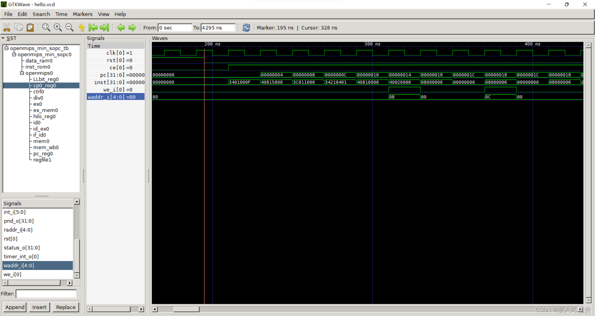
除了通用的pc、inst这些寄存器、wire之外,还可以把cp0_reg0里面的寄存器拉出来看看。重点看看we_i什么时候为高、写入的waddr_i对不对、和之前给出来的汇编代码能不能对的上。最后就是死循环了,因为mips延迟槽的原因,循环肯定是两个pc地址交替进行的。